
 ×

Dive into our diverse and informative blog, including latest industry trends, expert insights, and company updates.
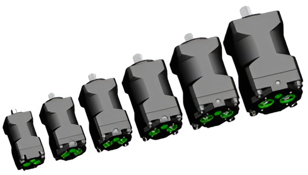
Understanding failure modes is essential for improving pump reliability. Typical failures include: Seal wear → caused by high pressure cycling Cavitation → due to poor inlet conditions Overheating → insufficient cooling Material fatigue → repeated stress loading Preventive strategies: Optimize inlet design Use high-performance sealing materials Implement thermal control Conduct lifecycle testing Reliability engineering is critical in mission-critical systems such as aerospace and defense.
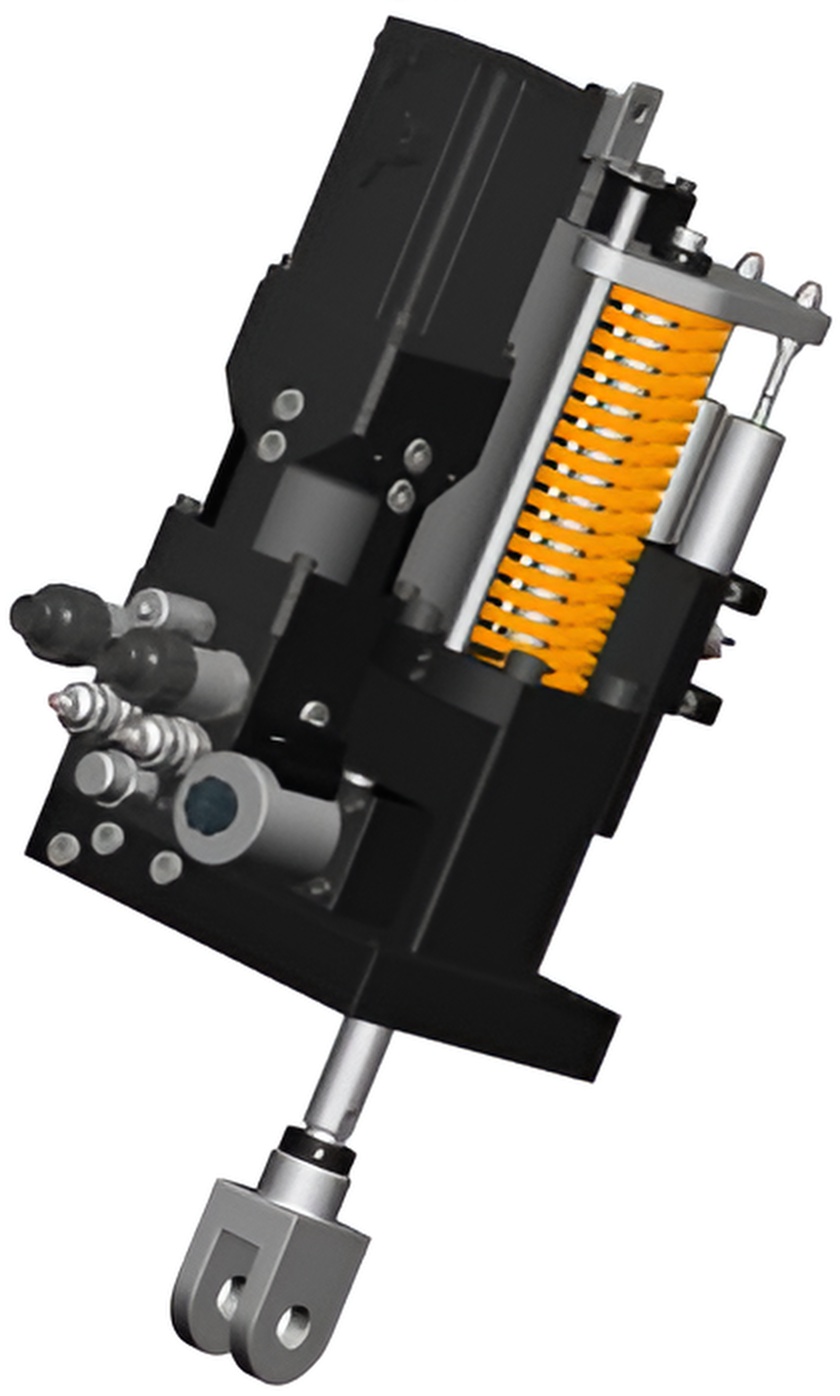
Electro-hydraulic actuators (EHA) are transforming motion control systems by eliminating centralized hydraulic infrastructure. Key advantages: No hydraulic power unit required Reduced leakage risk Improved energy efficiency Precise digital control Lower maintenance cost Key Technologies Motor-pump matching Thermal management Fast dynamic response Redundancy design EHA integrates pump, motor, reservoir, and actuator into a single unit, making it ideal for: Aerospace systems Autonomous robotics Industrial automation As electrification accelerates, EHAs are becoming a core solution for decentralized actuation.

Selecting the right micro piston pump for high-pressure applications requires more than just checking maximum pressure ratings. Engineers must balance performance, reliability, and system integration constraints. Key selection factors include: 1. Pressure vs. Flow Trade-off Higher pressure often reduces flow rate. Understanding system demand profiles is essential. 2. Efficiency at Small Scale Micro pumps operating above 30 MPa must minimize leakage and mechanical loss. 3. Material Compatibility Seal materials must withstand both pressure and fluid chemistry. 4. Thermal Management High-pressure operation generates heat, especially in compact systems. 5. Duty Cycle Continuous vs intermittent operation impacts pump lifespan. Micro piston pumps are increasingly used in aerospace, robotics, and portable hydraulic systems due to their compact size and high power density. “Contact us for custom high-pressure solutions”

Centrifugal pumps leverage the simple yet powerful mechanics of the impeller to efficiently transfer energy from the motor to the fluid, ensuring seamless flow in various applications. This blog will introduce centrifugal pumps. Fundamentals of Centrifugal Pumps Centrifugal pumps are essential for efficiently moving fluids by converting rotational kinetic energy into hydrodynamic energy. Key elements include impellers, which are crucial for driving fluid flow through the pump, and casings that manage and direct this flow. Understanding these components and forces involved is vital for leveraging them effectively in various applications. Principles of Operation Centrifugal pumps operate by using an impeller, which rotates to increase the fluid’s velocity. As the impeller spins, it imparts kinetic energy to the fluid, directing it outward from the pump center toward the casing. This outward motion creates a low-pressure region at the impeller's center, drawing more fluid into the pump. The casing is designed to convert the kinetic energy of the moving fluid into pressure. This is achieved by gradually slowing down the fluid in a way that increases pressure, allowing it to be efficiently transported through the system. This principle is vital for applications that require consistent fluid flow and pressure. Centrifugal Force and Fluid Movement Centrifugal force is central to the movement of fluid in a centrifugal pump. As the impeller rotates, centrifugal force drives the fluid outward, causing it to move through the pump's casing. This force increases the fluid's speed and ensures its movement from the inlet to the outlet. Fluid dynamics within the pump are influenced by the impeller's design, including its size and speed. These factors determine how effectively kinetic energy is imparted to the fluid. The force generated ensures a continuous and smooth flow, critical for maintaining system pressure and efficiency. Components of a Centrifugal Pump Key components of a centrifugal pump include the impeller, casing, and shaft. The impeller is the rotating part, usually designed with blades, that transfers energy to the fluid. Impeller design significantly affects flow and pressure levels within the pump. The casing is the stationary part that directs fluid flow into and out of the impeller. It's crucial for converting kinetic energy into pressure. Additionally, the pump's shaft connects the impeller to a motor or engine, facilitating rotation. Understanding these components is essential for optimizing pump performance and reliability. What We Offer The centrifugal pump impeller options available through our services reflect a commitment to quality and variety. By partnering with leading brands and offering a range of impeller types, Jaalink ensure that our clients find the perfect fit for their specific needs. Brands We Provide In the world of centrifugal pumps, brand reputation is crucial. Our selection includes top industry names known for their reliable and efficient pump impeller designs. Names like FLOWSERVE, SULZER, RUHRPUMPEN, ITT, GOULDS, KSB, and SUNDYNE demonstrate our dedication to offering only the best. Each brand brings its expertise to various impeller models, ensuring versatility and performance. These brands are favored for their innovative design approaches and use of high-quality materials. They provide tailored solutions across applications, from residential to industrial uses, ensuring efficiency and durability. With our offerings, clients have access to impellers that suit diverse operational needs and withstand challenging environments. Impellers Available Our inventory includes a variety of impeller types to cater to different demands. These impellers feature specific vane designs that affect flow and pressure, allowing users to select models best suited for their systems. Detailed attention to impeller design ensures optimal energy transfer and application-specific performance. Performance and Efficiency Understanding the performance and efficiency of a centrifugal pump impeller is crucial for optimizing its operation. This section provides detailed insights into how pump curves relate to operating points, the effects of cavitation and NPSH, and the importance of regular maintenance to minimize wear. Pump Curves and Operating Points Pump performance is represented by the pump performance curve, which shows the relationship between the flow rate and the head generated by the pump. Efficiency curves highlight the best operating point where the pump functions optimally. Identifying the optimal operating point maximizes energy efficiency and prolongs the pump's lifespan. Operators use these curves to ensure their pump operates at its most efficient range, thus reducing operational costs. A mismatch between the pump and system requirements can lead to problems like increased wear and decreased efficiency. Cavitation and NPSH Cavitation occurs when the pressure within a pump falls below the liquid's vapor pressure, causing vapor bubbles to form and implode, leading to damage. Ensuring adequate Net Positive Suction Head (NPSH) is vital to prevent cavitation. NPSH is the difference between the suction pressure and the liquid's vapor pressure. Maintaining the proper NPSH helps protect the impeller from excessive wear and performance loss. Monitoring and adjusting the system can mitigate cavitation risks and enhance pump performance. Maintenance and Wear Regular maintenance is essential to preserving pump efficiency and reducing wear and tear. Components such as seals, bearings, impeller rings and the impeller need inspection to prevent performance degradation. Neglecting maintenance can lead to increased maintenance costs, reduced efficiency, and even pump failure. Wear and tear can alter pump performance and efficiency, leading to operational challenges. Monitoring the condition of the pump and scheduling repairs when necessary can significantly enhance longevity and reliability. Employing these best practices ensures that centrifugal pumps remain efficient and effective over time. Selection and Application Selecting and applying a centrifugal pump impeller requires a clear understanding of the specific requirements and constraints of a given application. Different impeller types, flow characteristics, and installation concerns must be considered for optimal performance and efficiency. Choosing the Right Impeller The choice of impeller type—such as axial, radial, or mixed flow—depends largely on the desired flow characteristics and the nature of the fluid being pumped. Axial flow impellers are ideal for applications requiring high flow rates with low pressure, while radial flow impellers are used when high pressure is essential. The impeller diameter and clearance also play a critical role in determining performance. Ensuring proper impeller clearance minimizes energy loss and wear. Depending on the solids handling requirement, an open or closed impeller may be selected, with open impellers often chosen for pumping fluids with suspended solids. Decisions such as these must align with the specific pump selection criteria for efficient operation. Application-Specific Considerations Various application-specific factors, such as fluid type, desired pressure, and environmental conditions, drive impeller selection. Submersible pumps, for example, require specific types of impellers such as single suction or double suction designs that can handle contaminants without clogging. When selecting impellers, attention must be paid to potential recirculation issues, where fluid re-enters the pump, causing inefficiencies. Proper use of a strainer and maintaining appropriate bearings and volute configurations help mitigate these concerns. A thorough application of centrifugal pump impellers involves understanding the intricacies of each pump type and choosing an impeller that matches the operational demands of the system. Installation and Troubleshooting During installation, precise alignment of the pump system is crucial to avoid premature wear and leaks. Checking the impeller diameter and clearance ensures it meets the specified design parameters, reducing the risk of inefficiencies. Potential troubleshooting scenarios include dealing with cavitation or unwanted noise, often addressed by adjusting impeller clearance or verifying that the impeller type matches the fluid characteristics. Regular inspections and maintenance routines help ensure longevity. Adequate training for personnel in these practices can lead to more seamless operations and enhance overall pump system reliability.

Cavitation is a common issue in centrifugal pumps, where vapor bubbles form and collapse within the liquid being transported. Understanding and preventing cavitation is crucial for maintaining the longevity and performance of centrifugal pumps. This blog will give a sketch of cavitation and its role in centrifugal pumps. Fundamentals of Cavitation in Centrifugal Pumps Cavitation made by companies like Jaalink in centrifugal pumps involves the formation and collapse of vapor bubbles in a liquid. This phenomenon can lead to serious damage, including erosion and noise. Understanding its mechanics and effects is essential to mitigate potential impacts on pump performance. Understanding Cavitation Cavitation occurs when the local pressure in a liquid falls below its vapor pressure, creating vapor bubbles. These bubbles form primarily in low-pressure zones within the pump, often at the impeller. As they travel to higher pressure areas, they implode. This rapid pressure change generates shockwaves and can damage pump components significantly. A crucial aspect is the Net Positive Suction Head (NPSH), a measure of how much the suction side of a pump provides above the vapor pressure. Cavitation Mechanics The mechanical process of cavitation involves a cycle of bubble formation and collapse. When vapor bubbles enter regions of higher pressure, their sudden collapse produces intense shockwaves. These are capable of causing material erosion on pump surfaces. Over time, this erosion can lead to significant degradation of the pump, affecting its efficiency and lifespan. Additionally, the process generates both noise and vibration due to the turbulent flow created by collapsing bubbles. This turbulence can impact the stability of the pump system, increasing maintenance costs and reducing operational efficiency. Effects of Cavitation The effects of cavitation in centrifugal pumps are severe. Physical damage includes the erosion of the impeller, casing, and other internal components. Bubble collapse near metal surfaces results in pits and craters, compromising the integrity of the material. Moreover, cavitation leads to increased noise and vibration, affecting the pump's operational environment. Persistent cavitation can drastically reduce the efficiency of a pump, resulting in higher energy consumption. Therefore, identifying and addressing cavitation early is critical to maintaining optimal pump performance and avoiding extensive repairs. Understanding these factors is vital for engineers and technicians when designing and operating pump systems. Employing proper preventive measures ensures the longevity and reliability of centrifugal pumps. Analyzing Cavitation Impact on Pump Performance Cavitation significantly affects centrifugal pump operation, leading to potential damage and reduced efficiency. Understanding its influence is crucial for maintaining optimum performance and minimizing mechanical issues. Performance Metrics Affected by Cavitation Cavitation primarily impacts several key performance metrics of a centrifugal pump. The most immediate effect is a notable drop in pump efficiency, as cavitation disrupts the smooth flow of liquid through the system. Changes in flow velocity and pressure pulsations can lead to vibrations, which further degrade performance. Pump performance can also suffer due to variations in pressure distribution across the impeller blades. These fluctuations can lead to partial flow blockages and result in a reduction of the total discharge capacity. Furthermore, cavitation might hinder the pump's head capabilities, making it operate below its design specifications, especially in challenging conditions. A detailed analysis of cavitation-related performance changes often involves monitoring these metrics to identify potential issues early. Identifying Cavitation Damage Cavitation damage in pumps is commonly identified through visible signs on pump components, particularly the impeller. Impeller damage often manifests as pitting or erosion, caused by the violent implosion of vapor bubbles on the surfaces. Mechanical damage can also extend to bearings and seals, impacting overall pump reliability. Another sign of cavitation-related issues is unusual vibration levels. Increased vibrations indicate abnormal flow conditions, possibly due to cavitation-induced turbulence. These vibrations can be measured using sensors placed strategically within the pump system. Consistent monitoring for such changes helps in diagnosing cavitation problems before they escalate. Monitoring for Efficiency Loss To effectively manage cavitation and maintain pump efficiency, regular monitoring is essential. Modern pump systems frequently integrate sensors that track performance indicators, including vibration patterns and pressure changes. These sensors provide real-time data that can be analyzed to detect deviations from expected performance. Early detection of efficiency loss due to cavitation allows operators to make timely adjustments. Adjusting pump design parameters or optimizing operational conditions can significantly mitigate the adverse effects of cavitation. Regular maintenance checks that include inspection of impeller surfaces and system alignment further aid in sustaining pump efficiency over time. These proactive measures help prevent significant downtime and maintain optimal pump performance. Preventing and Managing Cavitation Ensuring efficient pump operation involves targeted strategies, thoughtful system design, and prudent pump selection. These steps reduce cavitation risks such as impeller damage and performance loss. Cavitation Prevention Strategies Cavitation can be minimized by maintaining a sufficient Net Positive Suction Head (NPSH). NPSH must be greater than the Net Positive Suction Head Required (NPSHr) for proper operation. Monitoring and increasing the available NPSH (NPSHa) can help prevent pump cavitation. Ensuring proper liquid flow and stable inlet conditions reduces pressure drops across impeller blades. Maintaining optimal flow rates is crucial, as low speeds minimize turbulence. Implement regular inspections to detect potential corrosion or recirculation issues in pump housing. System Design Considerations Designing systems with cavitation prevention in mind is essential. Adequate pipe sizing and layout can reduce head loss and pressure drop. Pump suction should be kept clear of obstructions to minimize turbulence at entry points. By positioning pumps below the liquid source, gravitational head can enhance NPSHa. Ensuring components are designed to handle fluctuating flow demands helps maintain pressure consistency and prevents cavitation. Clever design can integrate auxiliary systems that quickly respond to dynamic pressures, limiting impact on essential components. Therefore, system design directly affects cavitation management. Pump Selection and Operation Choosing the right pump involves more than specifications. Pumps designed specifically for high-risk environments will have features to prevent cavitation. Opting for the correct impeller design optimizes liquid flow and reduces kinetic energy losses. Collaboration with pump manufacturers ensures that pump speed matches operational needs. Slowing speeds slightly enhances performance stability. Regularly adjusting operations to stay within the pump’s design envelope will mitigate cavitation causes. Manufacturers often provide models with improved NPSH margins, which are crucial for applications with fluctuating atmospheric pressure or temperatures.

Quick connect air fittings are essential components for efficient pneumatic systems. Available in diverse materials like aluminum, brass, stainless steel, and nylon, quick connect fittings cater to specific operational needs. This blog will give an introduction to quock connect air fittings and relevant topics. Understanding Quick Connect Air Fittings Quick connect air fittings made by companies like Jaalink play a crucial role in pneumatic systems by enabling quick and efficient connections. These fittings come in various types and materials, each with specific compatibility and durability advantages. Types of Quick Connect Couplings Quick-connect air couplings are essential for various applications, including industrial and automotive uses. Industrial interchange quick-connect air couplings are popular due to their versatility and are often referred to as Milton-type or Type M couplings. These are commonly used in high-demand settings to ensure reliable connections. In contrast, high-flow couplings are designed to maximize airflow and are beneficial in situations requiring increased pneumatic power. These couplings are preferred in applications where a reduced pressure drop is necessary. Incorporating safety mechanisms, such as automatic lock features, ensures the secure detachment of hoses. Materials and Durability The material of a quick connect coupling significantly influences its durability and suitability for different environments. Brass quick-connect air coupling bodies are praised for their corrosion resistance and are often used in environments where moisture is a concern. Steel quick-connect air coupling bodies offer durability and strength, suitable for harsh conditions. Stainless steel quick-connect air coupling bodies provide both corrosion resistance and strength, ideal for demanding applications. Meanwhile, nylon quick-connect air coupling bodies present lightweight and flexibility, making them suitable for less industrial applications. Aluminum quick-connect air coupling bodies balance weight and durability, providing a middle ground between steel and nylon options. Compatibility and Interchangeability Ensuring compatibility and interchangeability is critical when selecting quick connect air fittings. Many couplings may appear similar but have differing specifications, such as size and thread type, which can affect their compatibility. Automotive, Tru-Flate, and T-style couplings are examples of fittings that may be referred to by multiple names despite having unique characteristics. Moreover, using couplings with different materials can also impact functionality and lifespan. It is essential to choose couplings that match with the intended system components, whether it's brass, steel, or another material, to maintain optimal performance. Regular checks for wear and tear contribute to long-term efficiency and safety. Engineering and Performance Quick connect air fittings play a critical role in optimizing air tool efficiency. They are engineered to minimize pressure drop and reduce air costs, embodying safety features such as sleeve guards and brass safety mechanisms. These aspects contribute to the overall functionality and reliability of pneumatic systems. Efficiency and Air Flow Efficiency is paramount in quick connect air fittings to ensure optimal tool performance. Multipurpose couplers are designed to maximize air flow, which is vital for maintaining the efficiency of pneumatic tools. These fittings often utilize high-quality materials like steel and brass, contributing to their durability and reliability. The industrial interchange design facilitates universal compatibility, allowing tools to connect easily and securely. By reducing pressure drop, these fittings enhance tool efficiency significantly. High-performance variants like the JACO Hi-Flo fittings exemplify this by providing consistent air supply to power tools. This optimization of air flow ultimately helps in lowering operational costs, offering a cost-effective solution for a variety of applications. Pressure Dynamics Pressure dynamics in quick connect air fittings involve managing the flow and pressure of air within pneumatic systems. These fittings are engineered to minimize pressure drop across connections, preserving adequate force for tool operation. High-flow couplings are particularly advantageous, as they boost air throughput and maintain steady pressure levels. Universal interchange quick-connect air couplings adjust effectively to different systems, ensuring consistent pressure. Furthermore, industrial interchange designs cater to a wide range of pneumatic needs by providing adaptability without compromising on performance. Maintaining pressure stability is crucial. It reduces energy consumption, cuts air costs, and prolongs tool lifespan. These fittings are integral to efficient and sustainable pneumatic tool operation. Safety Features Safety is a critical consideration in the design of quick-connect air fittings. Brass safety exhaust quick-connect air couplings incorporate features like sleeve guards to protect against accidental disconnection under pressure. This prevents injuries and equipment damage, ensuring secure and reliable connections at all times. Various safety mechanisms are built into these fittings to enhance operational security. Industrial interchange brass safety exhaust quick-connect air couplings are popular for their robust design and reliability in industrial settings. Overall, the integration of such safety features into quick connect air fittings provides users peace of mind, ensuring safety without sacrificing performance. Connecting and Operating Procedures This section focuses on the essential aspects of using quick connect air fittings with compressed air supplies, touching on how to attach and detach fittings, maintain them, and understand relevant terms and conditions. It is critical for ensuring effective and safe operation, whether dealing with air tools or industrial applications. Attaching and Detaching Attaching quick connect air fittings requires aligning the male hose barb with the female nptf end. It’s crucial to ensure the o-ring is in place within the fitting body for a secure seal. Once aligned, pushing the male end into the female connector until the collar locks it in place is necessary. This action ensures a firm connection without leaks, crucial for operations involving paint sprayers or blow guns. Detaching involves pressing the release button, allowing the collar to retract and safely disengage the fitting. This method prevents accidental disconnection and damage. Always check the pressure status of the air supply system before detaching to avoid sudden bursts of compressed air. Follow these steps to maintain a safe and efficient working environment. Maintenance and Troubleshooting Regular maintenance of quick connect couplings prolongs their lifespan and ensures efficient operation. Cleaning equipment regularly helps prevent debris accumulation that can disrupt air flow and compromise the connection integrity. Lubrication of internal components aids in smooth attachment and detachment cycles. Troubleshooting common issues involves identifying leaks or difficulty in connection. Ensure the o-ring is intact and free of wear. If leaks persist, examine the fnpt mnpt connections for any cross-threading or damage. Replace worn parts promptly to maintain proper operation. Adhering to these practices will reduce downtime and extend the equipment's operating life. Terms and Usage Understanding specific terms like FNPT (Female National Pipe Taper) and MNPT (Male National Pipe Taper) aids in selecting the appropriate fittings for industrial interchange plugs or air tools. The female npsf and male hose barb are vital in ensuring compatibility with various air systems. Awareness of these terms and conditions of usage ensures that connections are tight and secure, reducing the risk of air leakage in systems. Using correctly specified components with terms like hose barb or quick-connect air coupling plugs guarantees operational efficiency and safety. This understanding forms the foundation for optimal use of air fittings across different applications.
Trust in our expertise, every detail we unveil.
We'll keep you up-to-date on our latest products, services, and events.You'll have the opportunity to engage with us and connect with other like-minded individuals in our community. Click the links below to join us on Youtube, Instagram, Pinterest, and Facebook.


 Home
 Product
 Industries
 About